
9 Digital Technology 1
Section outline
-
Kia ora...
My name is Mr Taha and I am going to be your digital technology teacher throughout the year.
In this course we are going to explore and use wide variety of electronic components in circuits. We will start this week by learning about computational thinking.


Google classroom code:

Learning Intentions: We are learning to (WALT)...
Understand the basics of computational thinking
understand the binary numbers with a link to how computers work
Success Criteria: I can/have...
- use computational thinking to write a simple program on a computer using logical steps
Activities:
Computational thinking - task1
Binary numbers - task2
Homework:
use Scratch app to extend your code to a more complex one. -
Kia ora...
This week we will learn about Binary numbers and their role in computers.

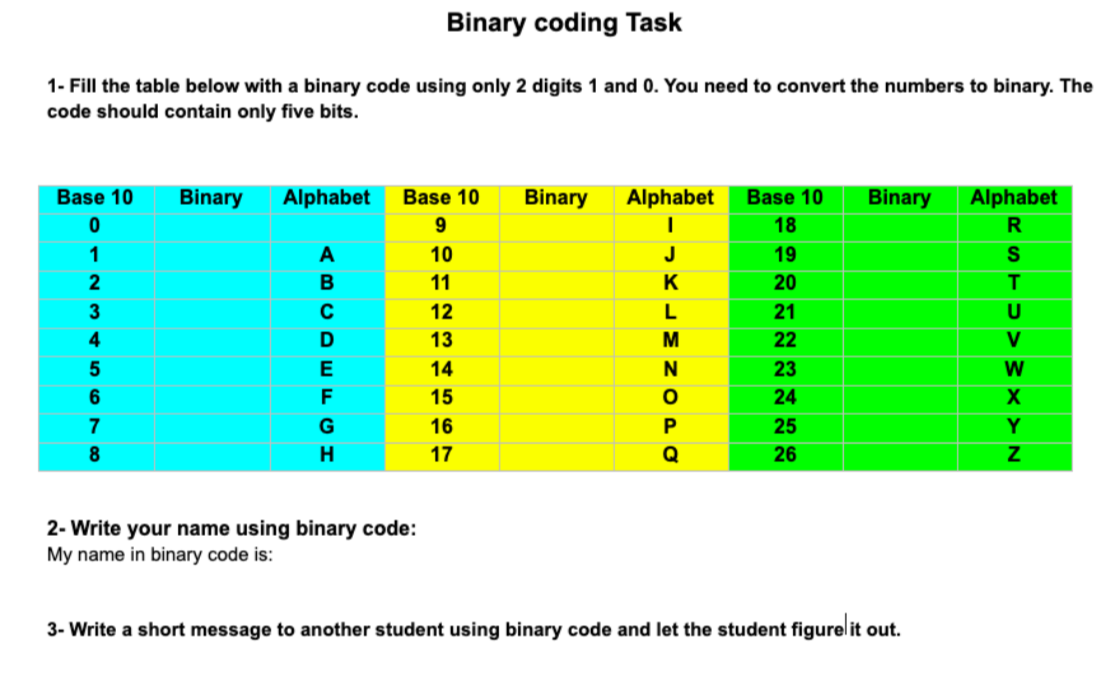
Success Criteria:
I can convert numerals into binary numbers and vise versa.
Activities:
- Binary numbers activity on google classroom
Further Learning:
Extend your knowledge of binary numbers by converting larger numerals to binary:
https://www.youtube.com/watch?v=FrsgHUSZ_ pc -
Kia ora...
This week we will learn about electronic components and their symbols and use.
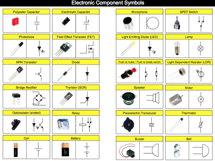
Success Criteria:
I can identify electronic components and their symbols in a circuit and explain their use.
Activities:
- Electronic components and their symbols activity on google classroom
Further Learning:
Extend your knowledge of electronic symbols by visiting Technology Student websiteLhttps://www.technologystudent.com/elec1/elecex.htm
-
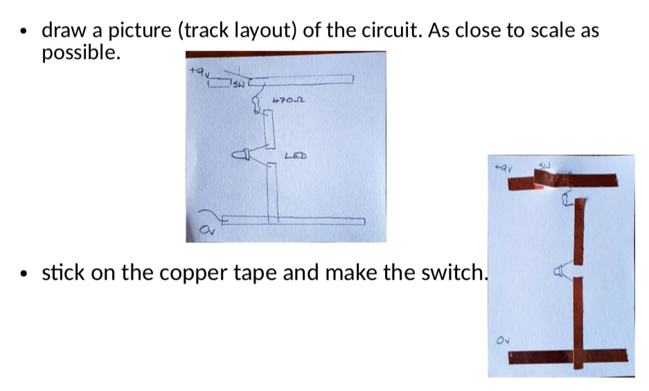
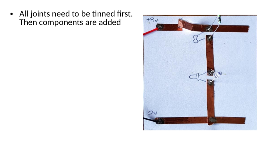
Kia ora...
This week we will start to construct our firs LED circuit using Tinkercar software and then with electronic components with breadboard. we will also use soldering to make an actual circuit on cardboard.
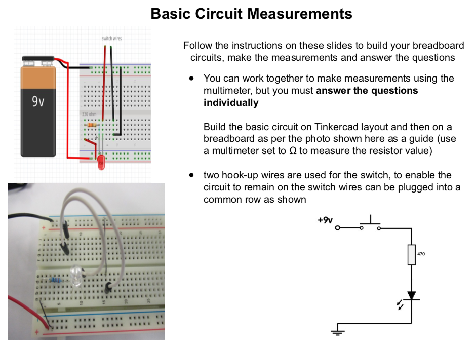
Success Criteria:
1- I can draw a simple LED circuit on Tinkercad : https://www.tinkercad.com/things/6pCm4c0kQ0I-surprising-hango/editel?tenant=circuits
2- I can construct a simple LED circuit using breadboard and electronic component
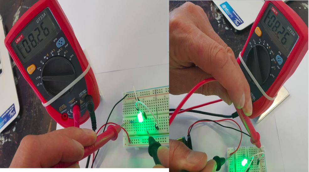
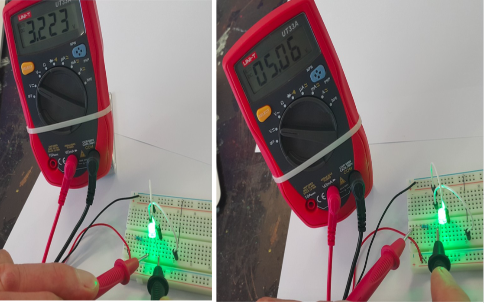
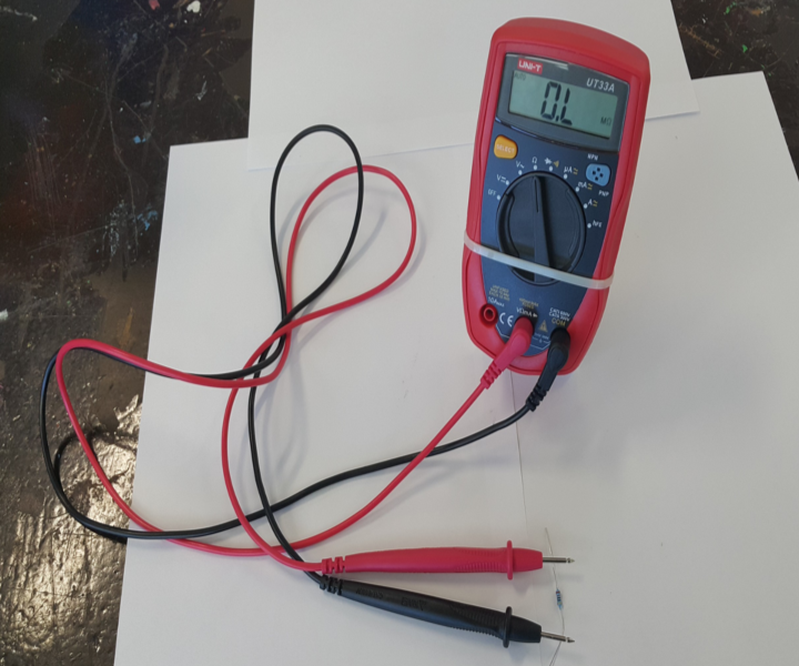
3- I can use the multimeter to measure voltage, resistance, current and continuity circuits
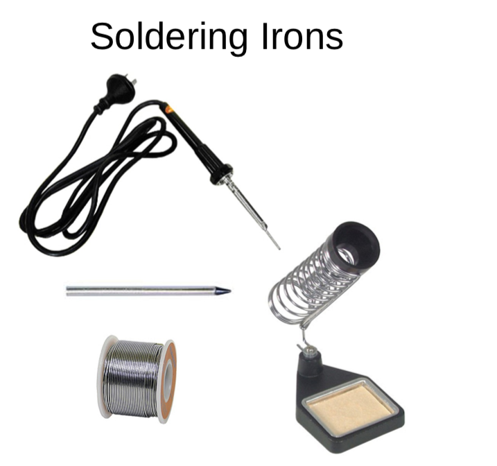
4- I can solder correctly and safely.
Activities:
- Link to Simple Electric circuit :
- Visit Simple LED circuit in the introduction to digital technology document.
- Practical activity of soldering
Further Learning:
Write here... -
Kia ora...
This week we will start to construct our firs LED circuit using Tinkercar software and then with electronic components with breadboard. we will also use soldering to make an actual circuit on cardboard.
Success Criteria:
- I can construct a simple LED circuit using breadboard and electronic component
- I can use the multimeter to measure voltage, resistance, current and continuity circuits
- I can solder correctly and safely.
Activities:
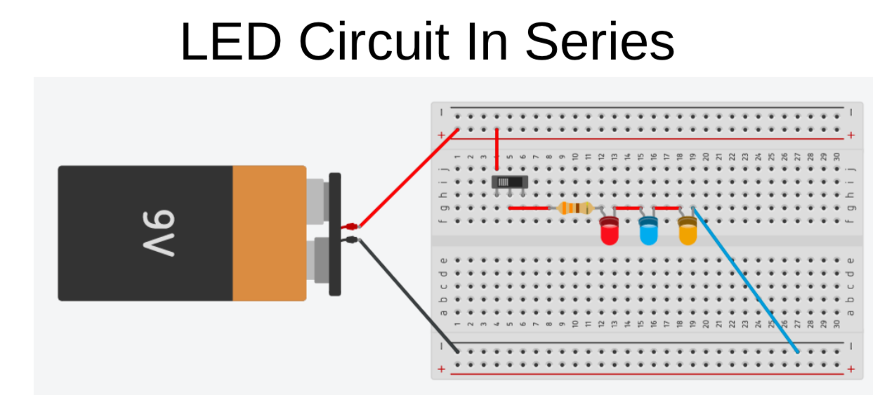
- Visit Simple LED circuit in the introduction to digital technology document.
- Practical activity of soldering
-
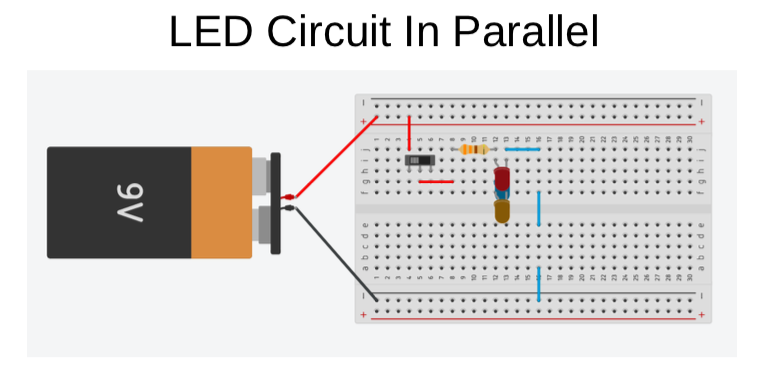
Kia ora...
This week we will continue working on construct our firs LED circuit using Tinkercar software and then with electronic components with breadboard. we will also use soldering to make an actual circuit on cardboard. We will then look at the difference between parallel and series circuits.
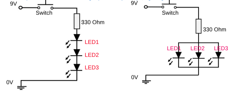
Success Criteria:
- I can construct a simple LED circuit using breadboard and electronic component
- I can use the multimeter to measure voltage, resistance, current and continuity circuits
- I can solder correctly and safely.
- I know the difference between parallel and series connection in a circuit in terms of voltage
Activities:
- Visit Simple LED circuit in the introduction to digital technology document.
- Practical activity of soldering
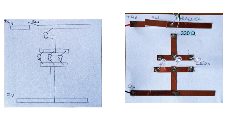
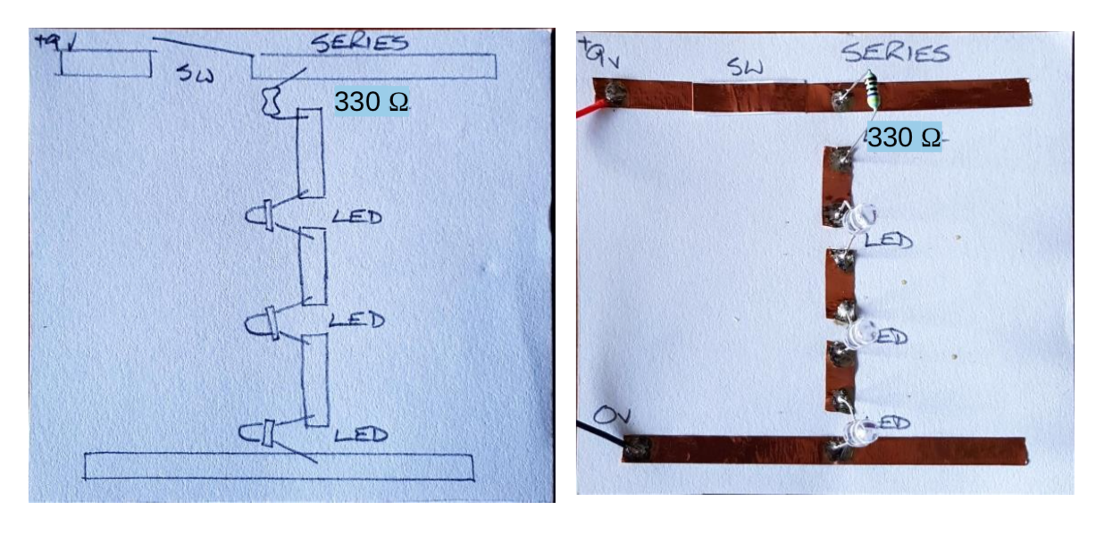
- Parallel and series circuits
-
Kia ora...
This week we will continue working on construct our firs LED circuit using Tinkercar software and then with electronic components with breadboard. we will also use soldering to make an actual circuit on cardboard. We will then look at the difference between parallel and series circuits.
Success Criteria:
- I can construct a simple LED circuit in series connection using breadboard and electronic component
- I can use the multimeter to measure voltage, resistance, current and continuity circuits
- I can solder correctly and safely.
- I know the difference between parallel and series connection in a circuit in terms of voltage
Activities:
- Visit Simple LED circuit in the introduction to digital technology document.
- Practical activity of soldering
- Parallel and series circuits
-
Kia ora...
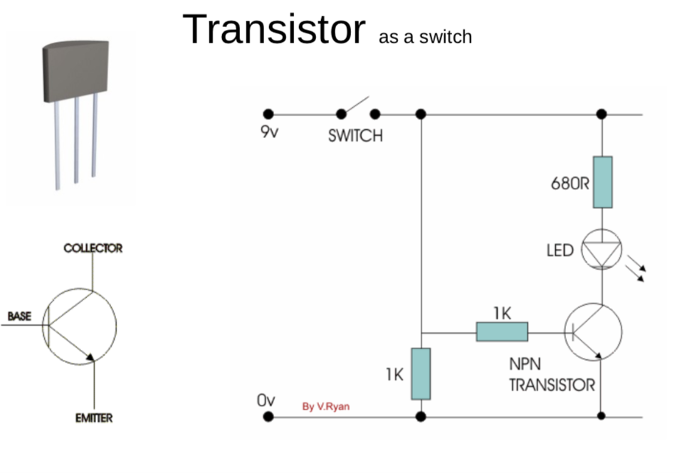
This week we will learn about the transistor component and it's circuit. We will build the circuit using Tinkercar software and then with electronic components with breadboard. we will also use soldering to make an actual circuit on cardboard.
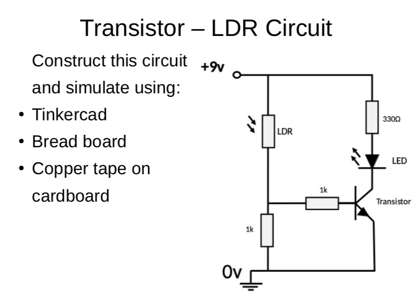
Success Criteria:
- I can construct a simple transistor - LDR - LED circuit using breadboard and electronic component
- I can use the multimeter to measure voltage, resistance, current and continuity circuits
- I can solder correctly and safely.
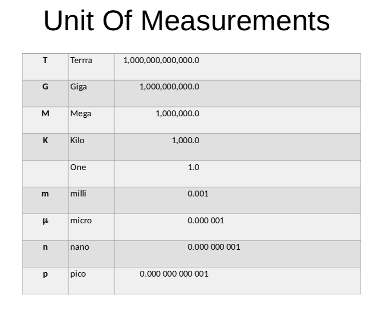
- I know the differet units of measurement
Activities:
- Use Tinkercad to draw the transistor LDR LED circuit and then construct using breadboard
- Practical activity of soldering
-
Kia ora...
This week we will learn about the Capacitor component and it's circuit. We will build the circuit using Tinkercar software and then with electronic components with breadboard. we will also use soldering to make an actual circuit on cardboard.
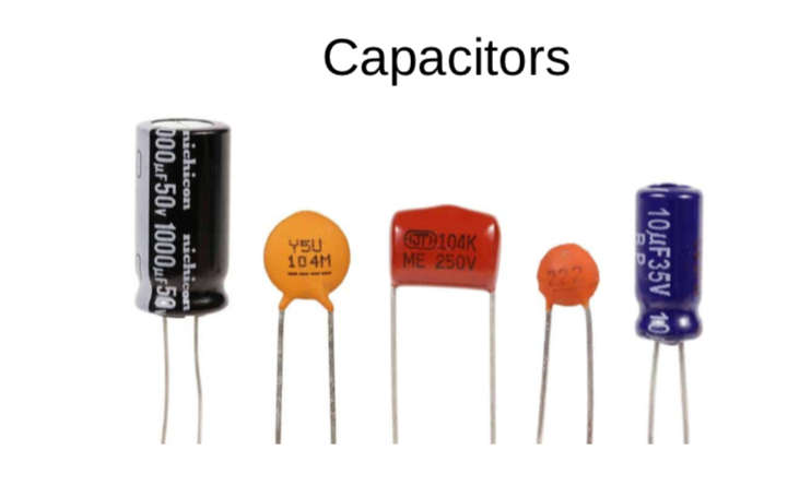

Success Criteria:
- I can construct a simple Capacitor - transistor - LED circuit using breadboard and electronic component
- I can use the multimeter to measure voltage, resistance, current and continuity circuits
- I can solder correctly and safely.
- I know the differet units of measurement
Activities:
- Use Tinkercad to draw the Capacitor - transistor - LED circuit and then construct using breadboard
- Practical activity of soldering
-
Kia ora...
Welcome back to the digital technology course. I hope you have had a great school break and recharged your batteries for a new term.
Welcome to term2.
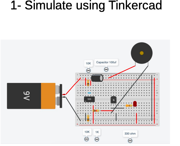
This week we will start learning about the 555 timer integrated circuits.


Learning Intentions:
use a 555 timer integrated circuit (IC) to operate an output for a specific amount of time
Success Criteria: I can/have...
construct a working prototype circuit using a 555 IC
Activities:
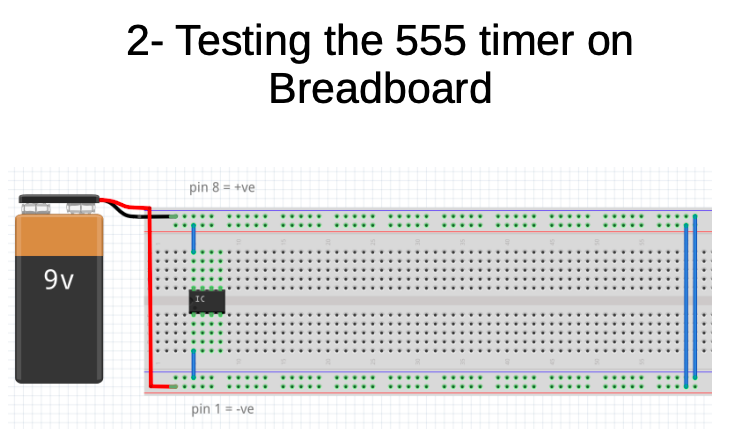
- insert the 555 into the breadboard, connect the power supply connections
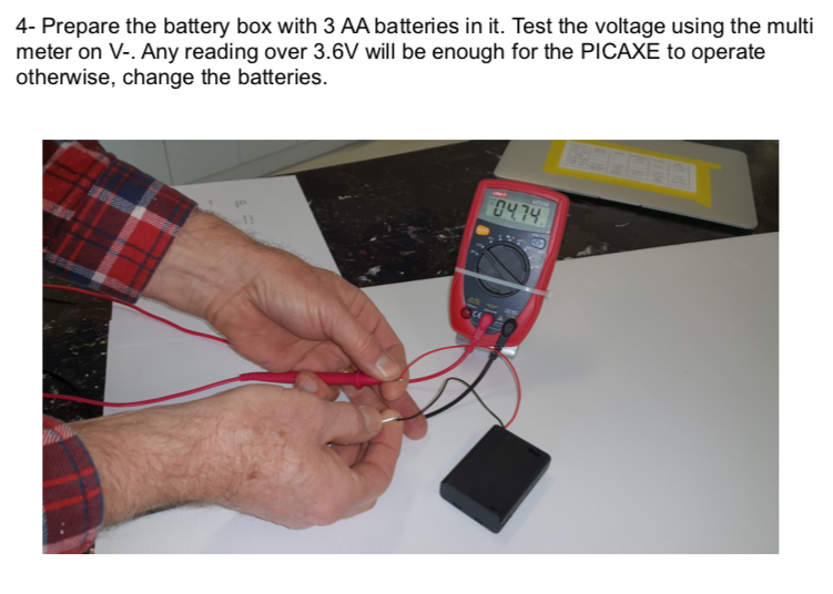
- test for a voltage between the power pins, pin 1 = negative and pin 8 = positive
- when a voltage has been established, disconnect the 9V battery
- look at the Tinkercad circuit diagram, learn the component symbols and where the components are connected to
- insert the components as per the bread board diagram - connection wires must be straight and flat on the board - NO SPAGHETTI WIRES
- the switch will be made from two pieces of hook-up wire
- test it, LED should be on and then off for about 1 second
You may find this website useful: http://www.555-timer-circuits.com/
diagrams and pictures are loaded on your weekly course page
-
Kia ora...
This week we will continue learning about the 555 timer integrated circuits.
Learning Intentions:
use a 555 timer integrated circuit (IC) to operate an output for a specific amount of time
Success Criteria: I can/have...
construct a working prototype circuit using a 555 IC
Activities:
- insert the 555 into the breadboard, connect the power supply connections
- test for a voltage between the power pins, pin 1 = negative and pin 8 = positive
- when a voltage has been established, disconnect the 9V battery
- look at the Tinkercad circuit diagram, learn the component symbols and where the components are connected to
- insert the components as per the bread board diagram - connection wires must be straight and flat on the board - NO SPAGHETTI WIRES
- the switch will be made from two pieces of hook-up wire
- test it, LED should be on and then off for about 1 second
You may find this website useful: http://www.555-timer-circuits.com/
diagrams and pictures are loaded on your weekly course page
-
Kia ora...
This week we will continue learning about the 555 timer integrated circuits. We will use the variable resistor (potectiometer) to control the time
Learning Intentions:
use a 555 timer integrated circuit (IC) to operate an output for a specific amount of time
Success Criteria: I can/have...
construct a working prototype circuit using a 555 IC
Activities:
- Visit google classroom with code:

- Complete the table shown in the document:
You may find this website useful: http://www.555-timer-circuits.com/
diagrams and pictures are loaded on your weekly course page
- Visit google classroom with code:
-
Kia ora...
This week we will continue learning about the 555 timer integrated circuits. We will use the variable resistor (potectiometer) to control the time
Big Idea:
Modelling a timer circuit using 555 timer
Learning Intentions:
use a 555 timer integrated circuit (IC) to operate an output for a specific amount of time
use mathematics to calculate a time constant
insert a transistor to operate an output
Success Criteria: I can/have...
- construct a working prototype circuit using a 555 IC
- I can vary the timing period by changing input components
- I can understand a time constant calculation
Activities:
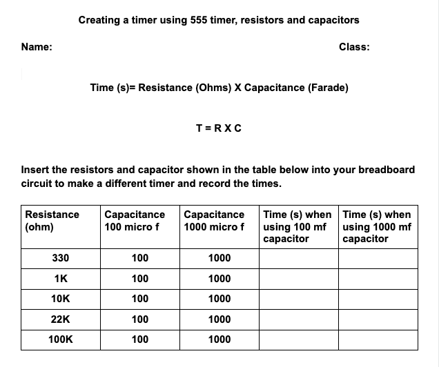
start a doc to record your findings - title will be 555 timer calculations
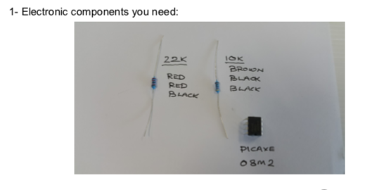
- remove the resistor on pin 7
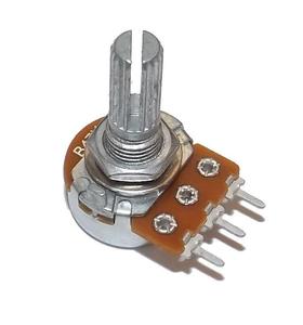
- insert a variable resistor on pin 7, (one wire to pin 7, one wire to +ve)
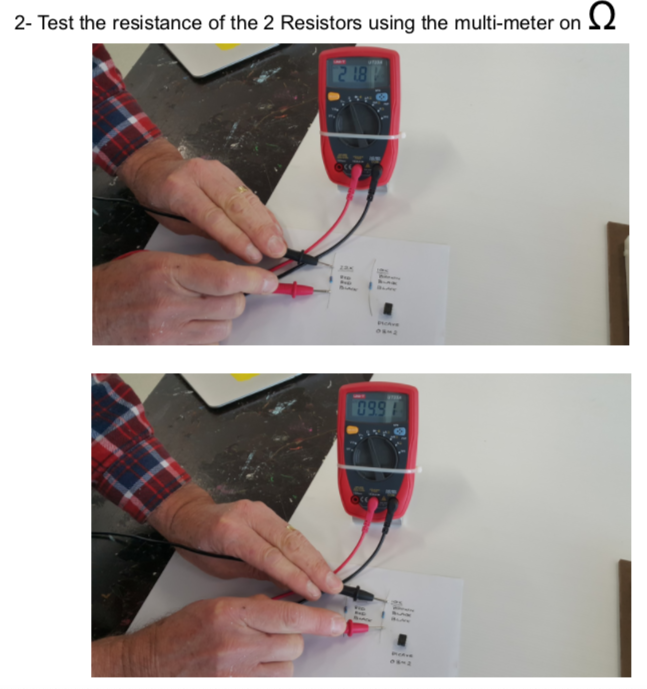
- remove the battery, resistance measurements can not be carried our while there is current flowing through the resistor as its resistance may be changing
- set a multimeter to measure resistance
- put the meter probes into the poles of the variable resistor
- turn the adjuster fully anti- clockwise - measure resistance
- turn the adjuster fully clockwise - measure resistance
what is the maximum resistance?
set the resistance to as near to 50K as possible, operate the timer, time the output period and note it
calculate the time constant using the formula of T = R x C
compare this calculated value of time with the actual time that the timer was operating (the actual time should be within 20% of the calculated time)
do the same with the VR set to 100K
extension exercise
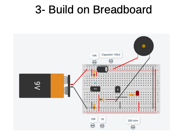
- insert a 1K resistor into the output pin 3
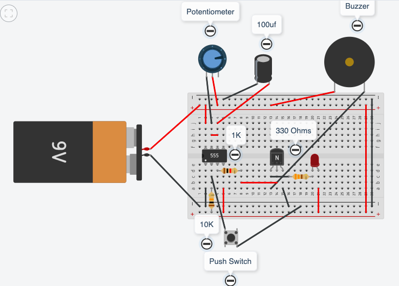
- insert a transistor, the base leg to connect with the 1K resistor (flat side of transistor to face towards the left side of the breadboard)
- connect a wire to link the emitter leg with -ve
- insert a RED LED, the -ve leg to the collector the +ve leg to +ve
- insert a 330/470 resistor between the red LED and the +ve of the breadboard
- connect a buzzer, the +ve lead to +ve, the -ve lead to the collector
- (you now have a transistor between pin 3 and +ve and a green LED between pin 3 and -ve)
operate the timer, when power is applied the red led and buzzer should be on. When timing begins the red led and buzzer will be off, the green led will be on until the timing sequence stops.
-
Kia ora...
This week we will continue learning about the 555 timer integrated circuits. We will use the variable resistor (potectiometer) to control the time
Big Idea:
Modelling a timer circuit using 555 timer
Learning Intentions:
use a 555 timer integrated circuit (IC) to operate an output for a specific amount of time
use mathematics to calculate a time constant
insert a transistor to operate an output
Success Criteria: I can/have...
- construct a working prototype circuit using a 555 IC
- I can vary the timing period by changing input components
- I can understand a time constant calculation
Activities:
start a doc to record your findings - title will be 555 timer calculations
- remove the resistor on pin 7
- insert a variable resistor on pin 7, (one wire to pin 7, one wire to +ve)
- remove the battery, resistance measurements can not be carried our while there is current flowing through the resistor as its resistance may be changing
- set a multimeter to measure resistance
- put the meter probes into the poles of the variable resistor
- turn the adjuster fully anti- clockwise - measure resistance
- turn the adjuster fully clockwise - measure resistance
what is the maximum resistance?
set the resistance to as near to 50K as possible, operate the timer, time the output period and note it
calculate the time constant using the formula of T = R x C
compare this calculated value of time with the actual time that the timer was operating (the actual time should be within 20% of the calculated time)
do the same with the VR set to 100K

extension exercise
- insert a 1K resistor into the output pin 3
- insert a transistor, the base leg to connect with the 1K resistor (flat side of transistor to face towards the left side of the breadboard)
- connect a wire to link the emitter leg with -ve
- insert a RED LED, the -ve leg to the collector the +ve leg to +ve
- insert a 330/470 resistor between the red LED and the +ve of the breadboard
- connect a buzzer, the +ve lead to +ve, the -ve lead to the collector
- (you now have a transistor between pin 3 and +ve and a green LED between pin 3 and -ve)
operate the timer, when power is applied the red led and buzzer should be on. When timing begins the red led and buzzer will be off, the green led will be on until the timing sequence stops.
-
Kia ora...
I hope you have had a great break
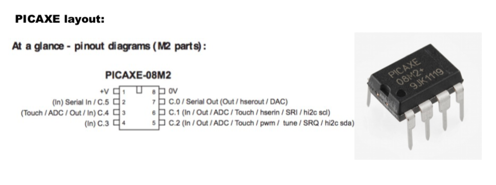
This term we will start learning about Picaxe microcontrollers. We will also learn basic java script to code the picaxe for different outcomes.

Software download:
● For Windows, Mac and Linux operating systems visit: http://www.picaxe.com/Software
● For Chromebooks and Tablet users:
Install the following programs on your Google account :-1. PICAXE Blockly (this allows you to write code for the PICAXE)
https://chrome.google.com/webstore/detail/picaxe-blockly/hhdlapnjifkkcpghcapopejopnbpapnb
2. PICAXE programmer (this allow you to program your PICAXE)
https://chrome.google.com/webstore/detail/picaxe-programmer/mcakegabnfookegpcpdmhgpdajgkjncp?hl=en-GB
To code on Chromebook click on the following link:
https://drive.google.com/a/mhjc.school.nz/file/d/0B9hRsiioOJuaM2hzVlFMLVZqZ1E/view? usp=sharing
Big Idea:
Moodlight using Picaxe
Learning Intentions:
begin programming a picaxe microcontroller
Achievement Objectives:
use a digital device to create an outcome
Success Criteria: I can/have...
- constructed a bread board with picaxe
- downloaded a programme
- worked through the programme examples
Activities:
we are beginning to learn programming of a microcontroller
- go to the website - picaxe
- go to the downloads section
- download the software, for windows it is 'programming editor 6, for Mac it is Axepad, for chromebook you need to access the app 'Boxy
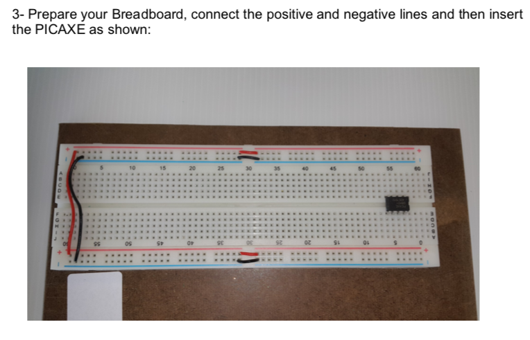
next stage is to set up your breadboard, this will be covered in class, test the setup, download and begin programming examples
-
Big Idea:
Designing and making moodlight using picaxe micro controller
Learning Intentions:
begin programming a picaxe microcontroller
Achievement Objectives:
use a digital device to create an outcome
Success Criteria: I can/have...
- constructed a bread board with picaxe
- downloaded a programme
- worked through the programme examples
Activities:
we are beginning to learn programming of a microcontroller
- go to the website - picaxe
- go to the downloads section
- download the software, for windows it is 'programming editor 6, for Mac it is Axepad, for chromebook you need to access the app 'Boxy
next stage is to set up your breadboard, this will be covered in class, test the setup, download and begin programming examples