
Term2 Week5
Section outline
-
Kia ora...
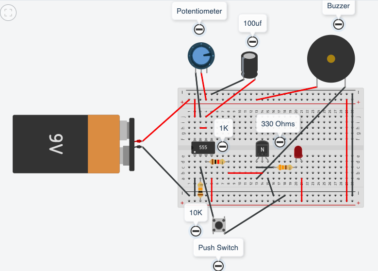
This week we will continue learning about the 555 timer integrated circuits. We will use the variable resistor (potectiometer) to control the time
Big Idea:
Modelling a timer circuit using 555 timer
Learning Intentions:
use a 555 timer integrated circuit (IC) to operate an output for a specific amount of time
use mathematics to calculate a time constant
insert a transistor to operate an output
Success Criteria: I can/have...
- construct a working prototype circuit using a 555 IC
- I can vary the timing period by changing input components
- I can understand a time constant calculation
Activities:
start a doc to record your findings - title will be 555 timer calculations
- remove the resistor on pin 7
- insert a variable resistor on pin 7, (one wire to pin 7, one wire to +ve)
- remove the battery, resistance measurements can not be carried our while there is current flowing through the resistor as its resistance may be changing
- set a multimeter to measure resistance
- put the meter probes into the poles of the variable resistor
- turn the adjuster fully anti- clockwise - measure resistance
- turn the adjuster fully clockwise - measure resistance
what is the maximum resistance?
set the resistance to as near to 50K as possible, operate the timer, time the output period and note it
calculate the time constant using the formula of T = R x C
compare this calculated value of time with the actual time that the timer was operating (the actual time should be within 20% of the calculated time)
do the same with the VR set to 100K
extension exercise
- insert a 1K resistor into the output pin 3
- insert a transistor, the base leg to connect with the 1K resistor (flat side of transistor to face towards the left side of the breadboard)
- connect a wire to link the emitter leg with -ve
- insert a RED LED, the -ve leg to the collector the +ve leg to +ve
- insert a 330/470 resistor between the red LED and the +ve of the breadboard
- connect a buzzer, the +ve lead to +ve, the -ve lead to the collector
- (you now have a transistor between pin 3 and +ve and a green LED between pin 3 and -ve)
operate the timer, when power is applied the red led and buzzer should be on. When timing begins the red led and buzzer will be off, the green led will be on until the timing sequence stops.